


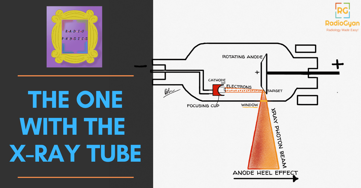
X-ray tube physics: the short version
An X-ray tube is an evacuated glass or metal envelope containing a heated tungsten filament (the cathode) and a tungsten target (the anode). Heating the filament boils off electrons; the kilovoltage across the tube accelerates them to the anode, where under 1% of their kinetic energy becomes X-rays and the rest becomes heat. Two design tricks dominate everything that follows: the anode is bevelled, so a large heat-absorbing actual focal spot projects as a small effective focal spot (the line focus principle), and it rotates, so the heat is spread around a track instead of a point. The price of the bevel is the anode heel effect: the beam is measurably weaker on the anode side of the field.
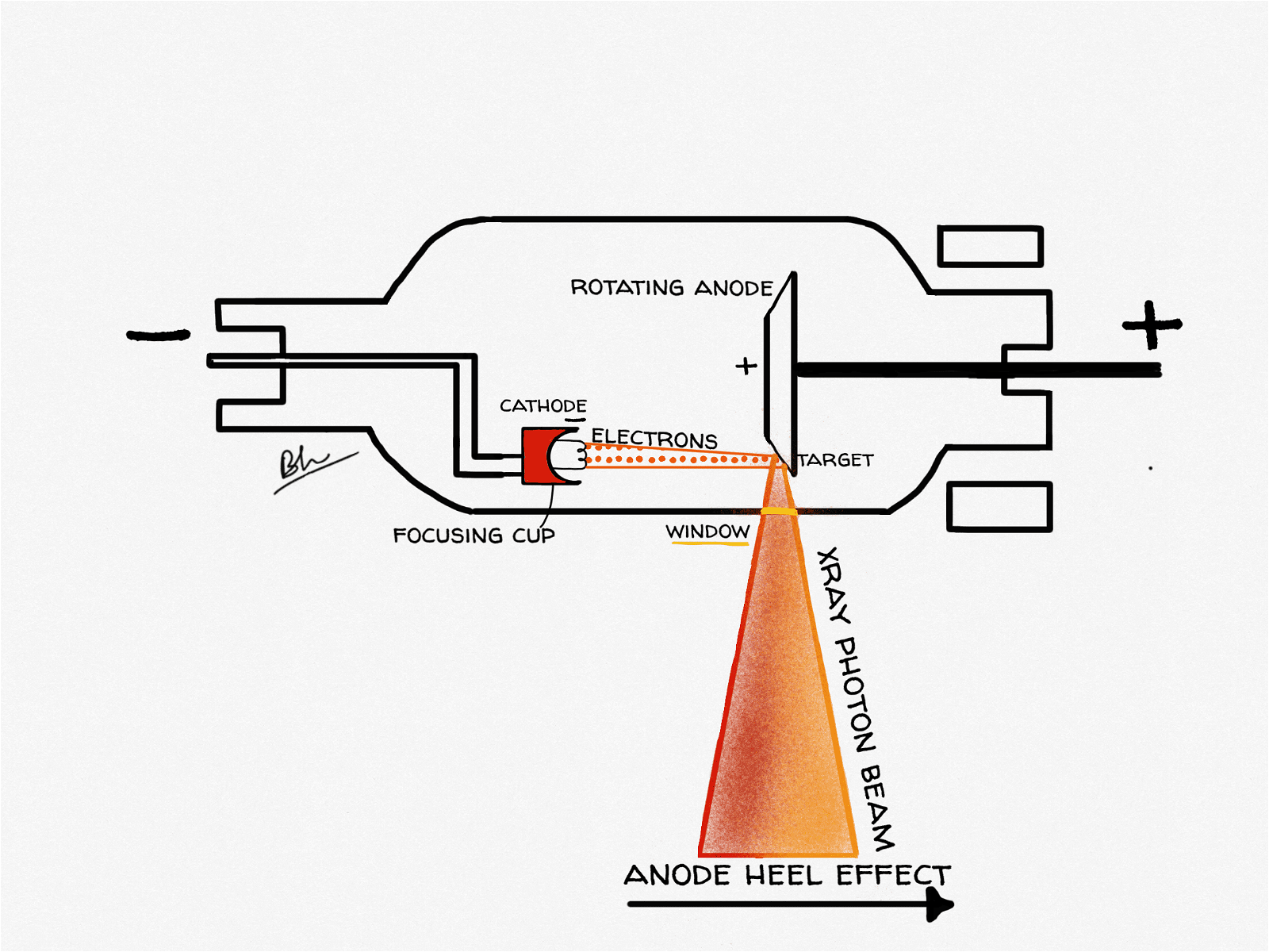
X-ray tube diagram: what each part does
| Component | Material / detail | Why it is made that way |
|---|---|---|
| Filament (cathode) | Thoriated tungsten coil, heated to roughly 2,200 °C | Tungsten has a very high melting point and low vapour pressure; thorium lowers the work function so more electrons are emitted per unit heat |
| Focusing cup | Negatively charged nickel or molybdenum cup around the filament | Electrostatically squeezes the diverging electron stream onto a narrow strip of the target |
| Dual filaments | Short filament and long filament in one cup | Gives a selectable small focal spot (detail) and large focal spot (heat capacity) from the same tube |
| Target (anode) | Tungsten alloyed with about 5%–10% rhenium, bonded to a molybdenum or graphite disc | Tungsten gives high atomic number (Z = 74) and a 3,422 °C melting point; rhenium resists surface crazing; molybdenum or graphite adds heat storage at low weight |
| Rotor and stator | Induction motor: rotor inside the envelope, stator coils outside | Spins the anode without any electrical connection crossing the vacuum seal |
| Envelope | Borosilicate glass or, in modern tubes, metal and ceramic | Holds the vacuum so electrons travel without colliding with gas molecules; metal envelopes trap stray off-focus electrons |
| Tube housing | Lead-lined, oil-filled | Oil conducts heat away and insulates; lead absorbs leakage radiation |
 Radiophysics humor: Illustrating the common sentiment that the field is complex and often misunderstood by others.
 A lighthearted teaching moment referencing the components and function of an X-ray tube, relevant to radiology physics education.
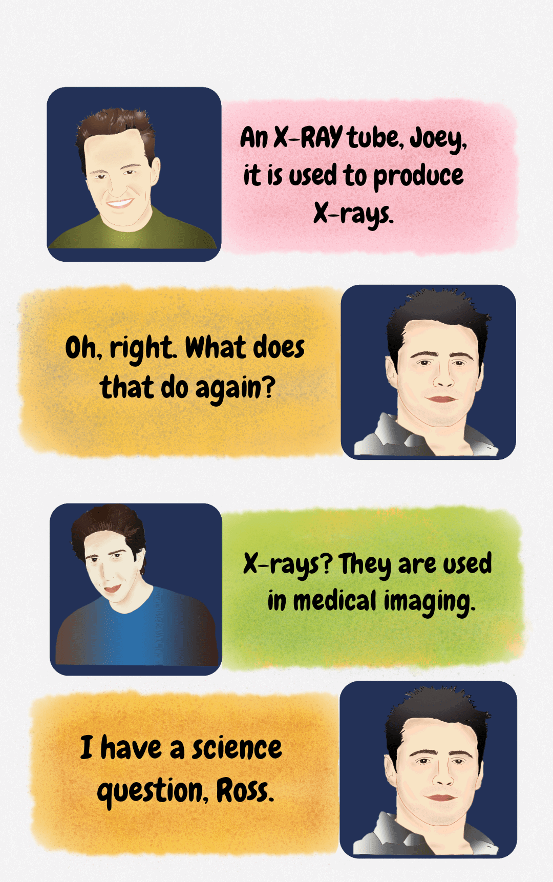 A lighthearted educational figure explaining that an X-ray tube is used to produce X-rays for medical imaging.
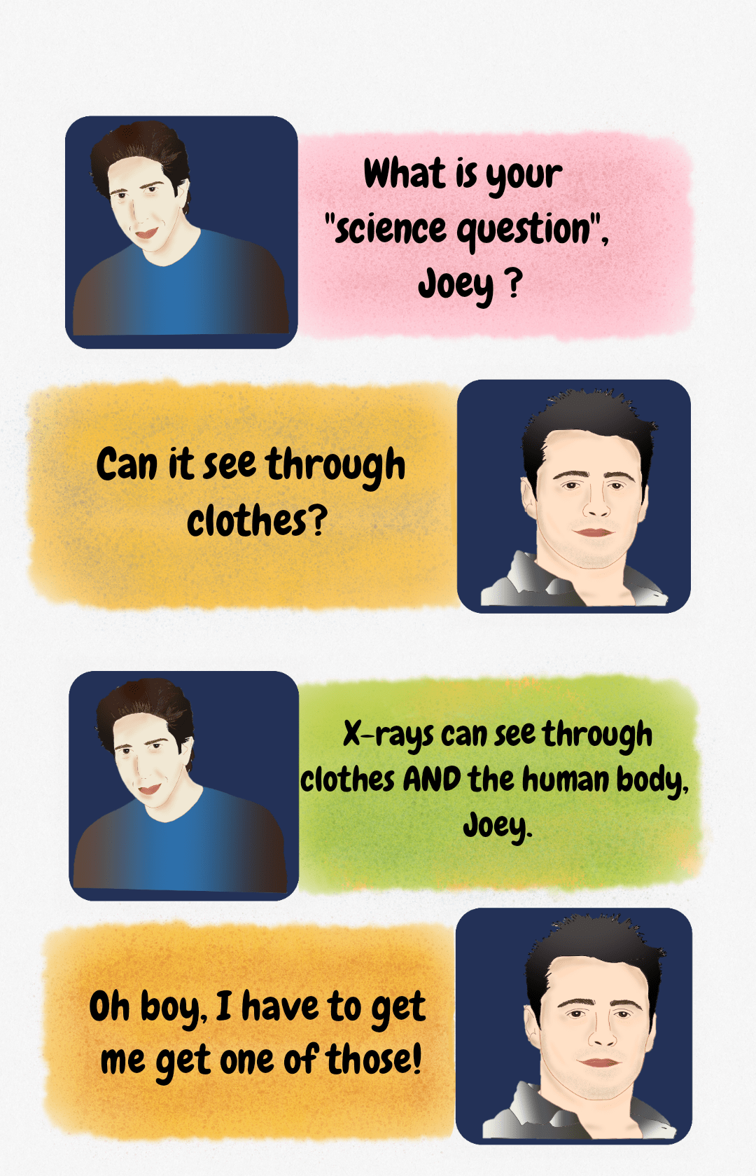 Humorous educational figure summarizing the basic concept of X-ray penetration capability, referencing the ability to see through clothes and the body.
 Meme-style educational figure illustrating the dynamic of explaining complex concepts, such as X-ray physics, to a less engaged audience.
 Humorous introduction to radiology physics: choosing to learn about the X-ray tube over distractions.
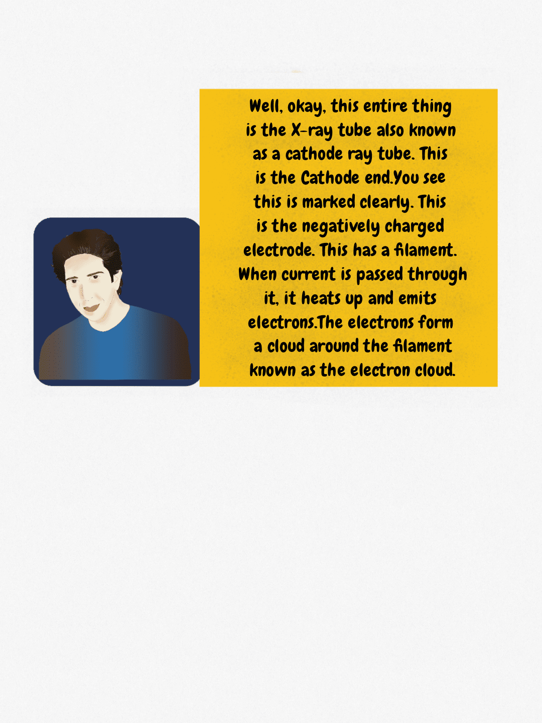 Explanation of the cathode end of the X-ray tube, detailing the role of the filament in generating the electron cloud.
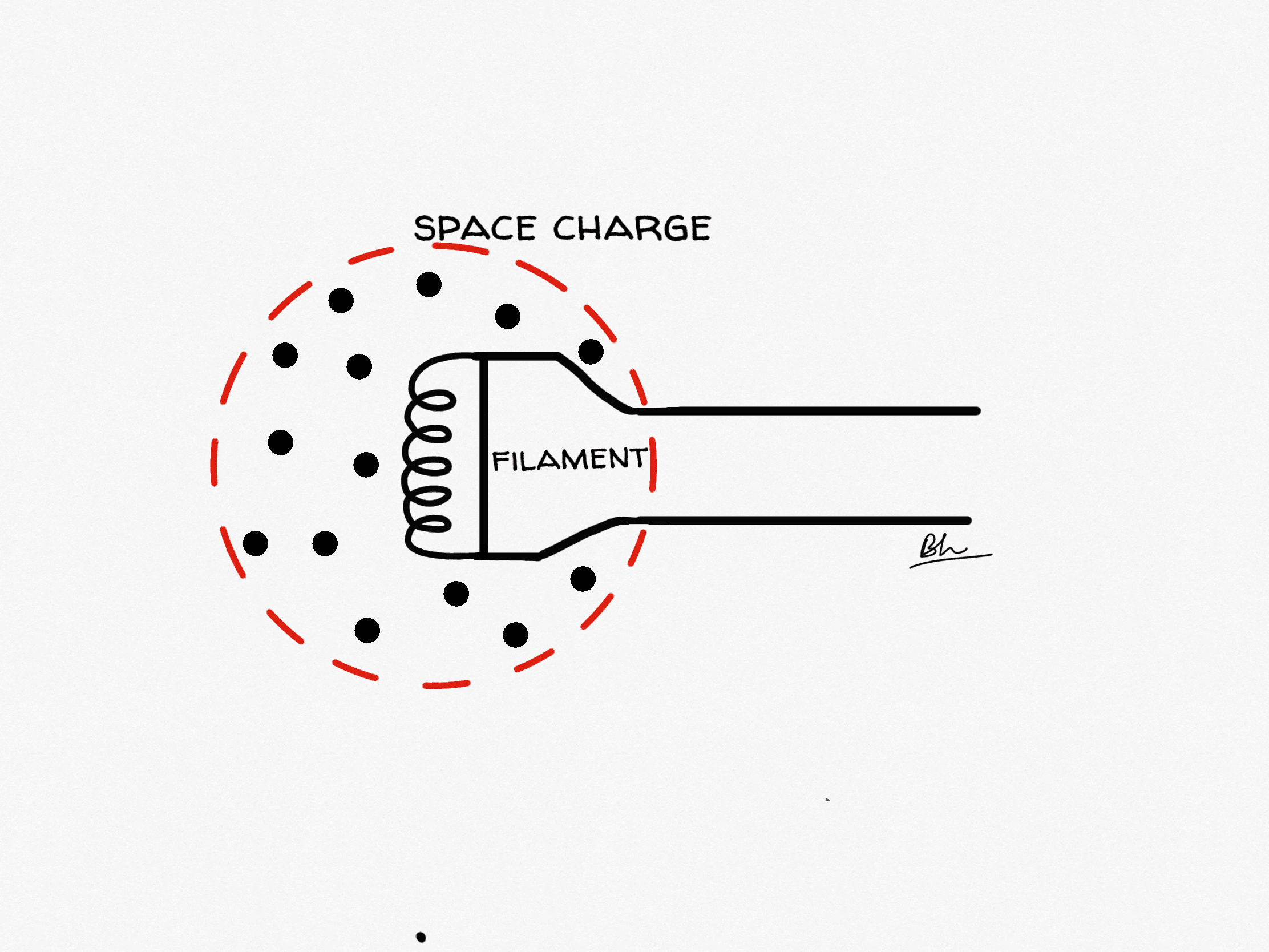
 Mnemonic-style diagram illustrating the space charge effect: the negative charge of the electron cloud limits further electron emission from the cathode.
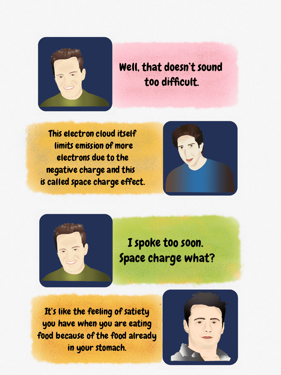
 Humorous diagram explaining the overcoming of the space charge effect in X-ray tube physics using Ross and Joey.
Thermionic emission and the space charge effect
Passing a filament current of a few amperes through the coil raises it to incandescence and electrons escape from the metal surface: thermionic emission. Before any kilovoltage is applied, those electrons hover as a negatively charged cloud just outside the filament. That cloud repels further electrons trying to leave, and the self-limiting result is the space charge effect.
This produces two distinct operating regimes, and knowing which one you are in explains several exam favourites:
- Space-charge-limited region (roughly below 40 kVp): the cloud, not the filament, limits the tube current. Raising kVp pulls more electrons out of the cloud, so mA climbs with kVp even at a fixed filament current. This is why generators apply space-charge compensation.
- Emission-limited (saturation) region (higher kVp): the applied voltage sweeps the cloud across as fast as it forms. Tube current now depends almost entirely on filament temperature, which is why mA is set by the filament circuit, not by kVp.
A practical corollary: because filament life falls steeply with temperature, modern generators keep the filament on a low standby current and boost it only during the rotor-prep stage, which is the delay you hear before the exposure.
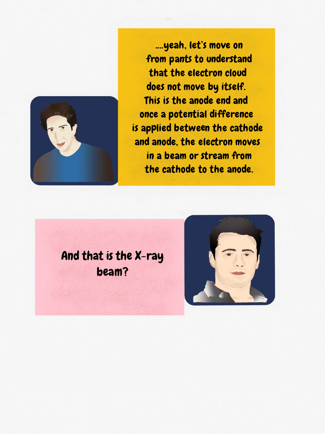 Explanation of electron stream generation in the X-ray tube, moving from the cathode to the anode after potential difference is applied.
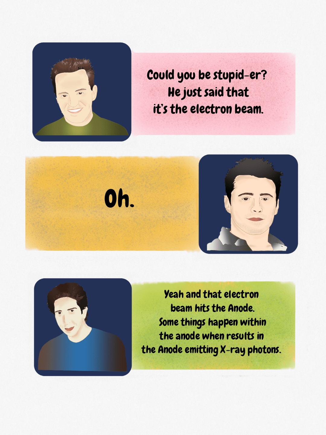 A teaching diagram explaining that the electron beam striking the anode results in the emission of X-ray photons, a key concept in X-ray physics.
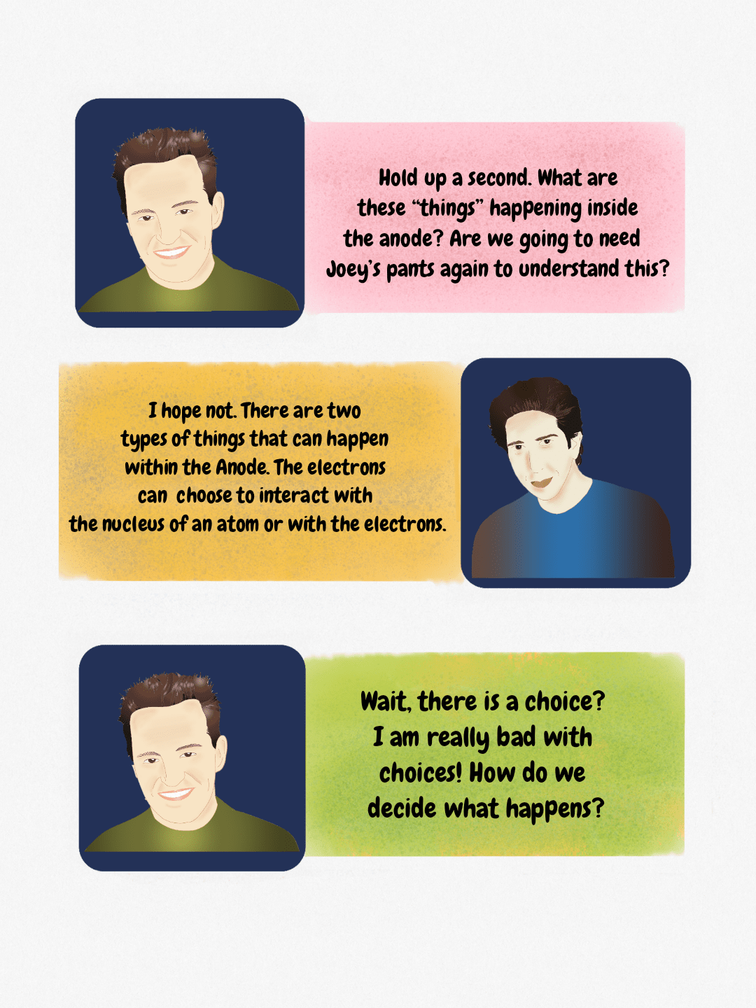 Dialogue explaining the two types of electron interactions occurring within the X-ray tube anode during X-ray generation.
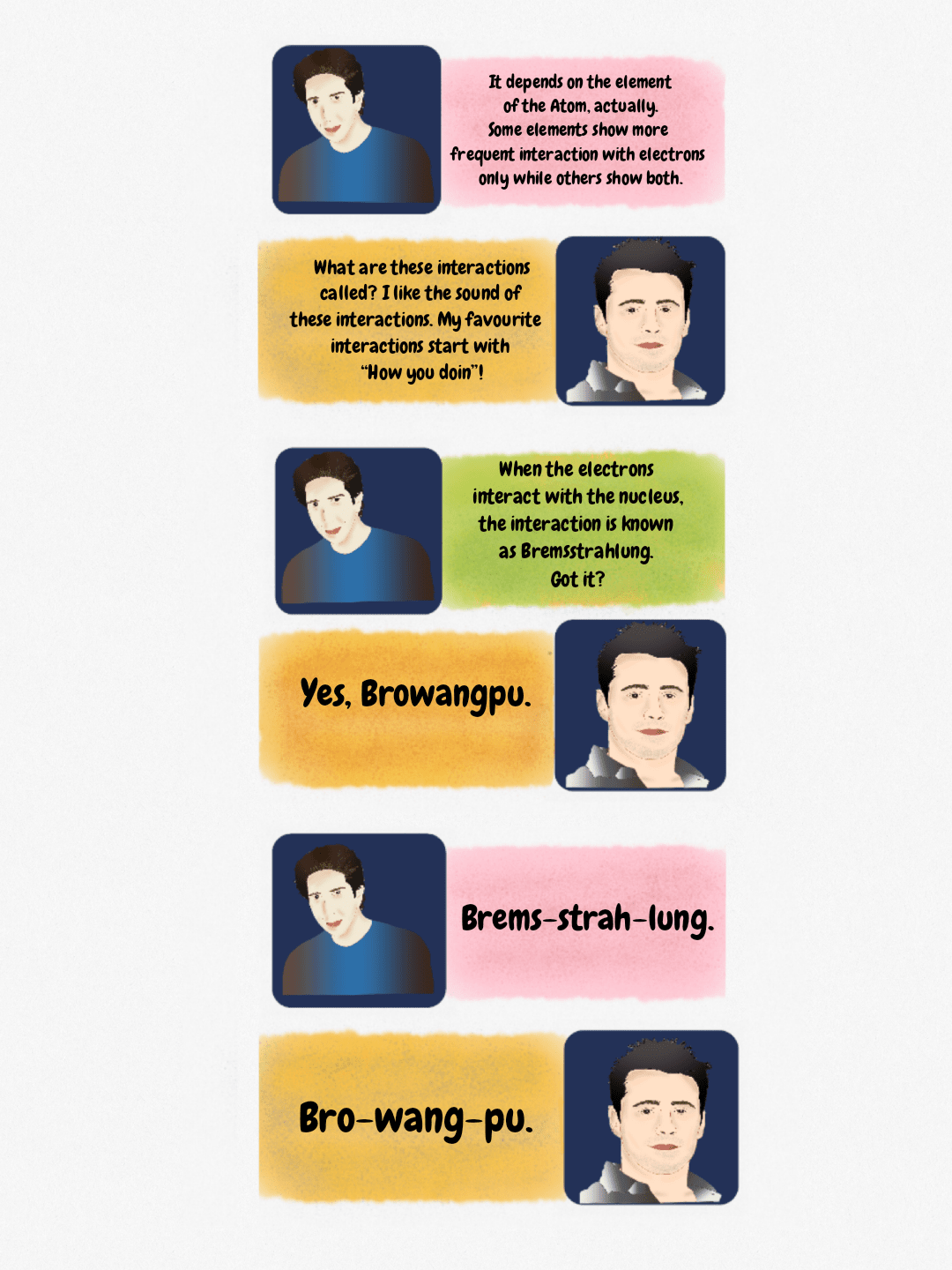 A humorous educational figure explaining X-ray production physics, including the term Bremsstrahlung, using characters resembling those from the TV show Friends.
 Mnemonic diagram breaking down the term Bremsstrahlung into its phonetic components for easier recall in radiology physics.
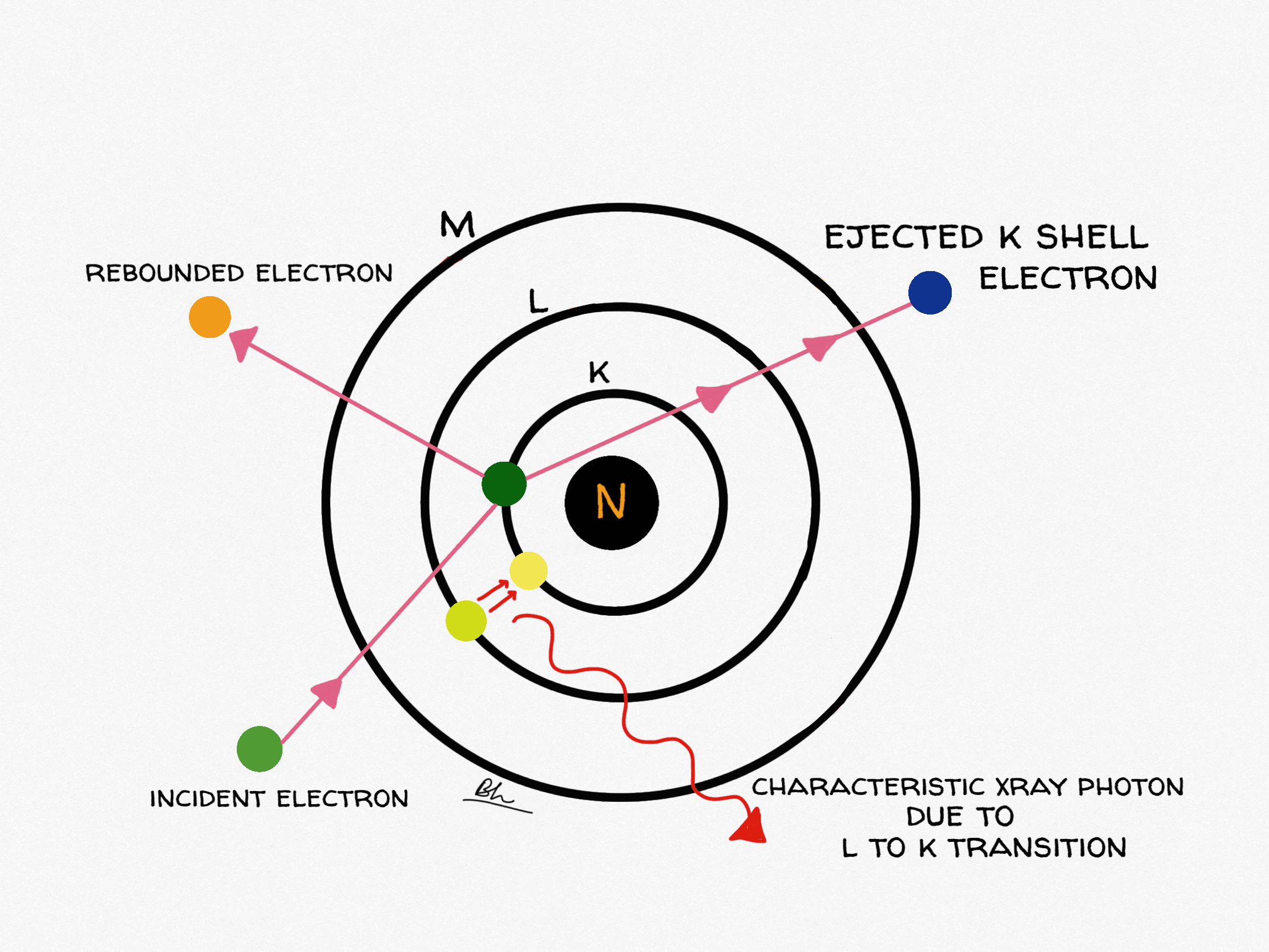
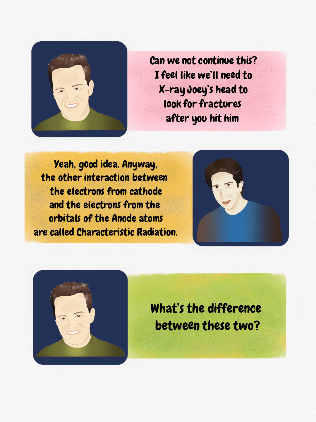 Comic panel explaining the mechanism of Characteristic Radiation in X-ray tube physics.
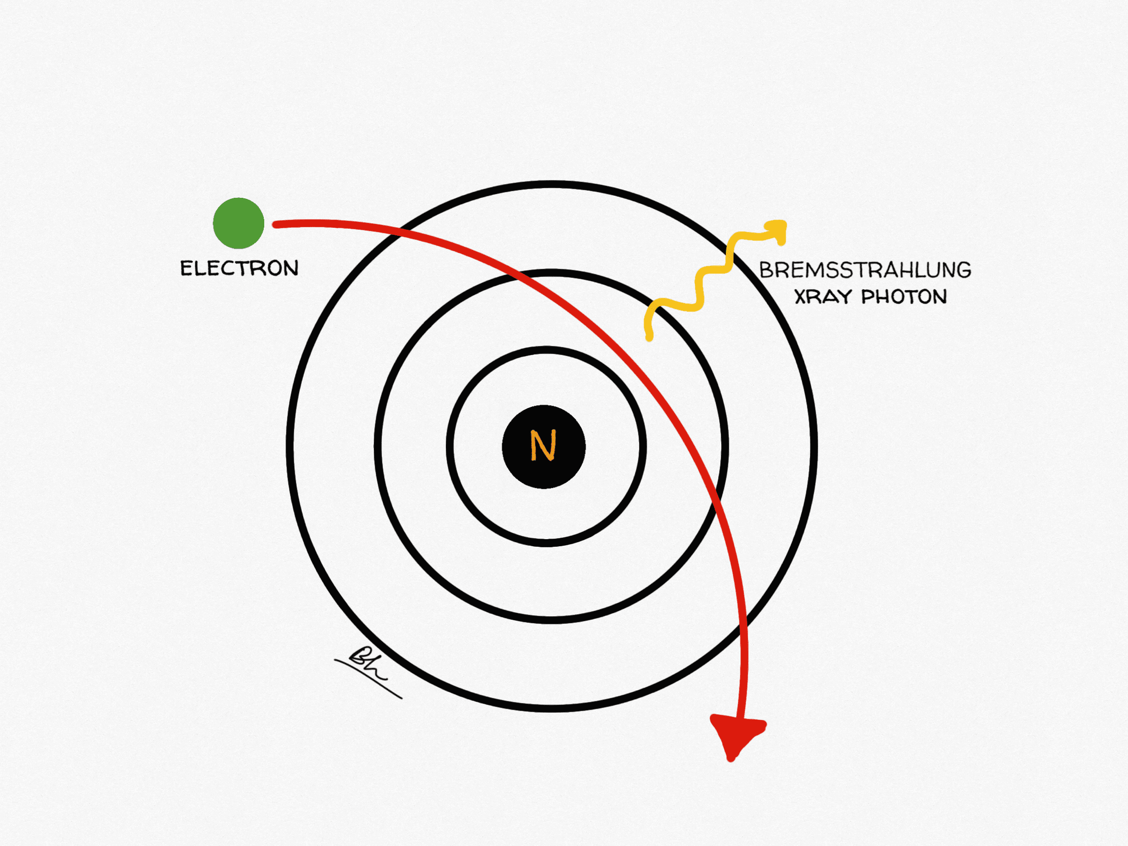
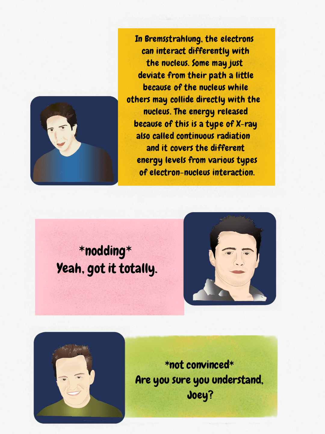 Diagram explaining Bremsstrahlung radiation, where electron deceleration near the nucleus produces continuous X-ray radiation.
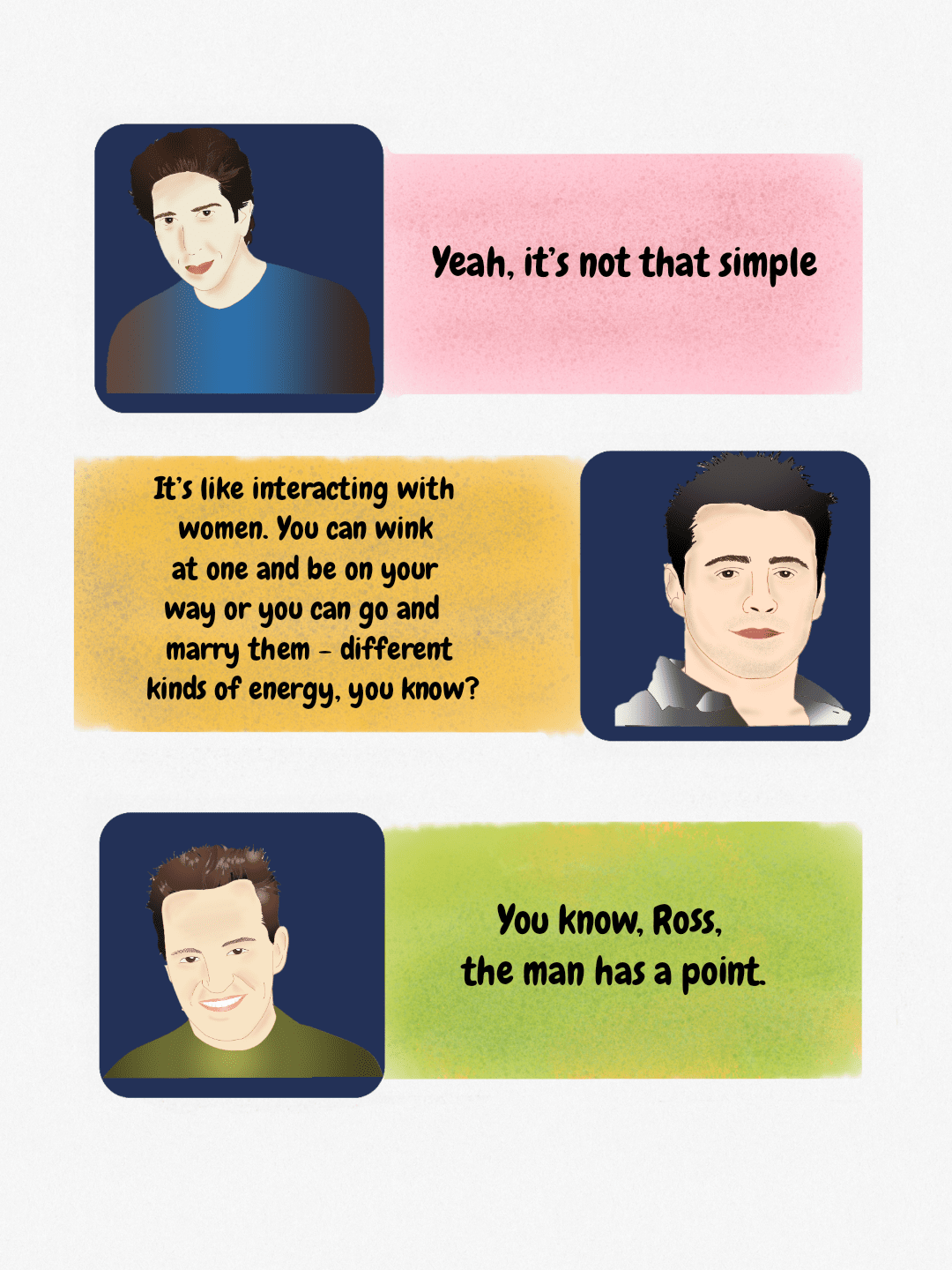 Dialogue illustration featuring characters from the TV show Friends, used here as an educational figure.
Bremsstrahlung versus characteristic radiation
Only two processes make the X-rays you use. Everything else in the target becomes heat: at 100 kVp with a tungsten anode, roughly 99% of the electron energy is wasted as heat and well under 1% leaves as X-rays.
| Bremsstrahlung | Characteristic radiation | |
|---|---|---|
| Mechanism | Incoming electron is decelerated and deflected by the positive nuclear field; the lost kinetic energy is emitted as a photon | Incoming electron ejects an inner-shell (usually K-shell) electron; an outer-shell electron drops in and the binding-energy difference is emitted as a photon |
| Spectrum | Continuous, from near zero up to a maximum equal to the peak kilovoltage | Discrete lines at fixed energies determined by the target element |
| Tungsten energies | Maximum photon energy in keV equals the kVp selected | K-alpha near 58–59 keV, K-beta near 67 keV (K-shell binding energy 69.5 keV) |
| kVp threshold | Produced at any kVp | No K-characteristic radiation below about 69.5 kVp, because the electron cannot eject a K-shell electron |
| Share of output | The large majority of a diagnostic beam | About 10% of tungsten-target output at 100 kVp, rising to roughly 25% at 150 kVp; none at all below 69.5 kVp |
Two things follow directly. First, an unfiltered spectrum is dominated by low-energy photons that would only add skin dose, which is why inherent plus added filtration (typically 2.5 mm aluminium equivalent above 70 kVp) is mandatory. Second, mammography deliberately chooses different targets (molybdenum has K-lines at 17.5 and 19.6 keV, rhodium at 20.2 and 22.7 keV) because at those energies characteristic radiation lands exactly where soft-tissue contrast is best.
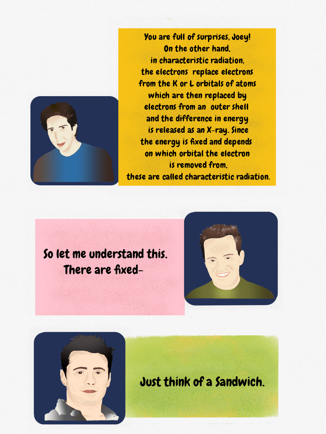 Diagram explaining characteristic radiation: fixed energy X-rays released when outer shell electrons fill vacancies in K or L orbitals.
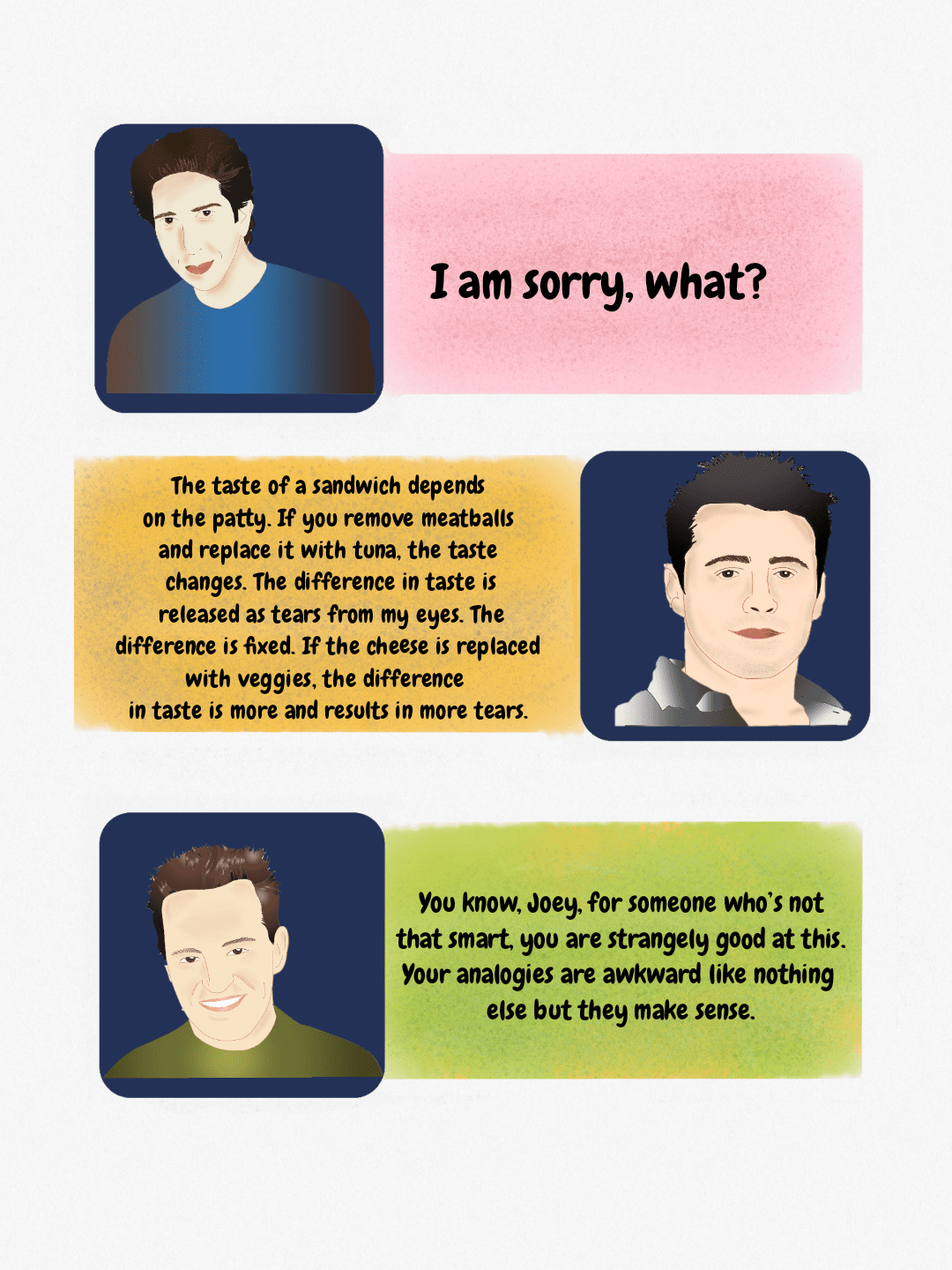 A humorous analogy involving sandwich ingredients and tears, used to explain a concept, featuring illustrations of Ross, Joey, and Chandler.
 A teaching diagram using pop culture references to illustrate key steps in X-ray generation, such as emission from the anode and subsequent filtration.
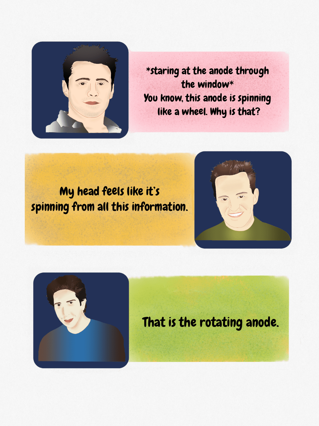 A simplified dialogue explaining the rotating anode component of an X-ray tube, referencing its spinning motion.
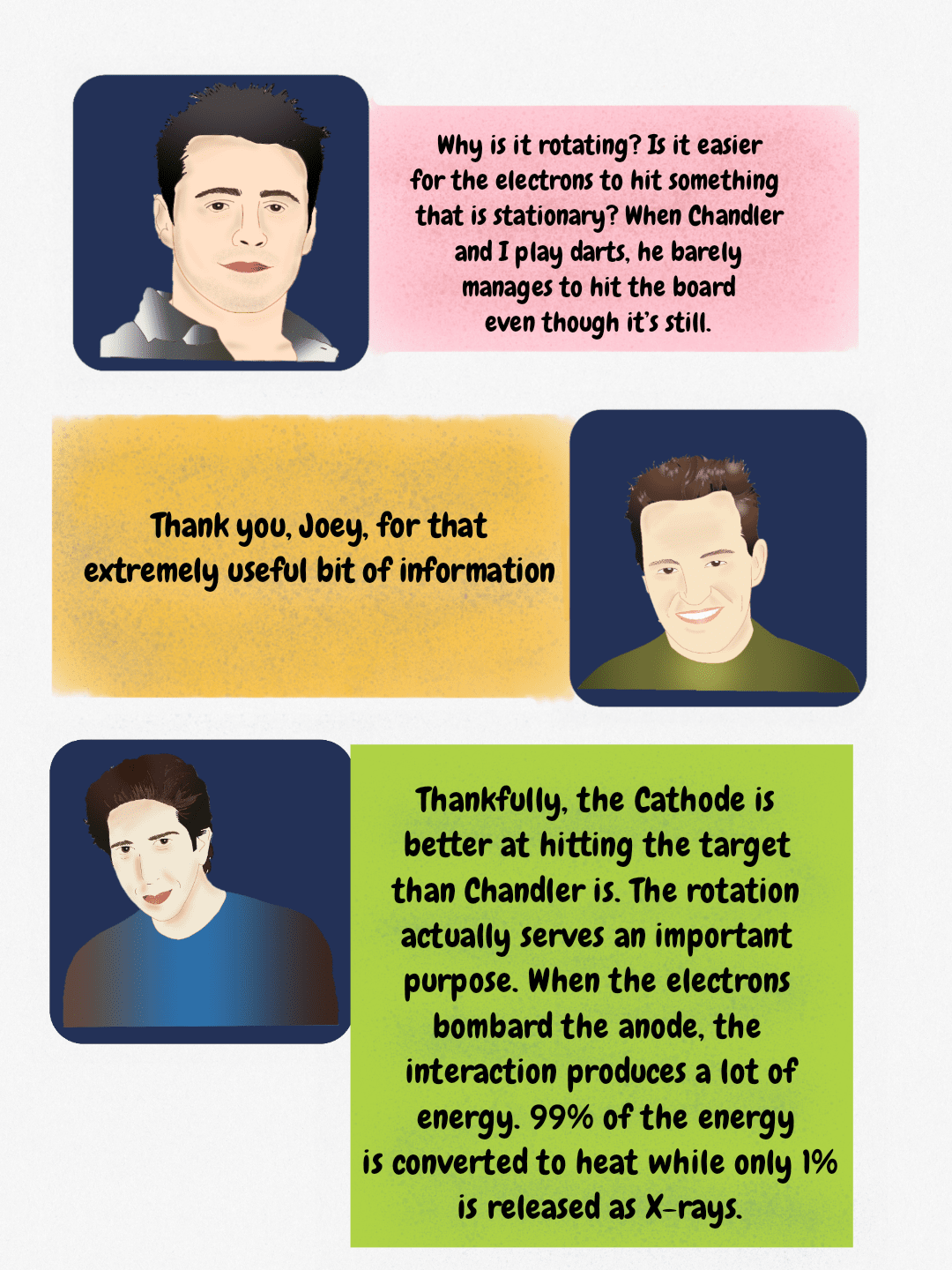 Illustration detailing X-ray tube physics, including the role of the rotating anode and the energy conversion ratio during electron bombardment of the anode.
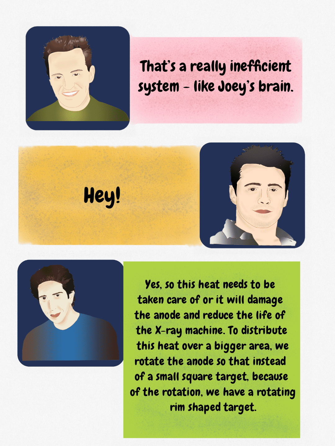 The rotating anode distributes heat generated during X-ray production over a larger surface area to protect the X-ray tube components.
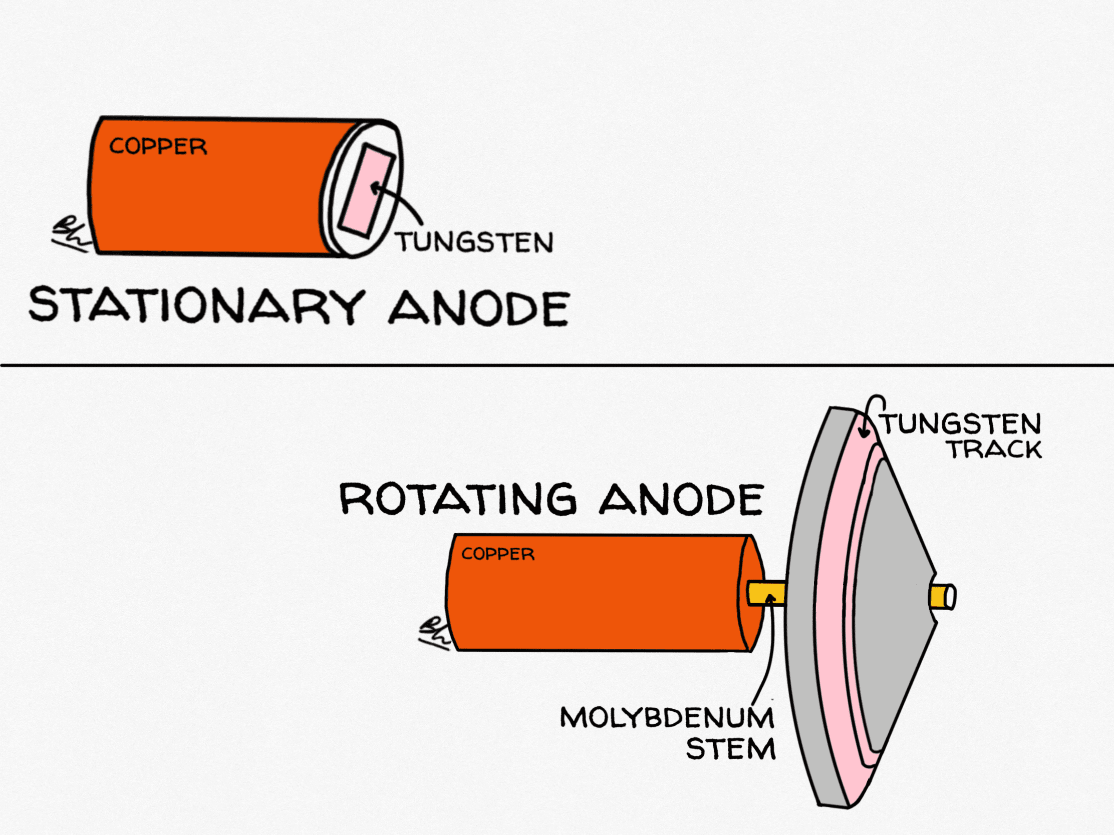
Stationary anode versus rotating anode X-ray tube
Heat, not physics, is the limiting factor in tube design. A stationary anode concentrates every exposure onto the same few square millimetres of tungsten. A rotating anode spreads the same energy around a circular focal track, increasing the area heated by about two orders of magnitude and allowing far higher tube currents.
| Feature | Stationary anode | Rotating anode |
|---|---|---|
| Target | Tungsten button set into a copper block | Tungsten-rhenium focal track on a molybdenum or graphite disc, 70–125 mm diameter |
| Heat loading | Low: the same spot is bombarded every time | High: energy is distributed around the whole focal track |
| Rotation speed | None | About 3,000–3,600 rpm standard; 8,000–10,000 rpm in high-speed tubes |
| Typical focal spot | Larger, often 1–2 mm | 0.3–0.6 mm small focus, 0.8–1.2 mm large focus |
| Cooling | Conduction into copper, then oil | Mostly radiation from the disc; convection in rotating-envelope designs |
| Where you see it | Dental units, mobile and portable units, some fluoroscopy | General radiography, CT, angiography, mammography |
Tube loading is quoted in heat units. For a single-phase generator, heat units equal kVp multiplied by mA multiplied by exposure time; three-phase and high-frequency generators multiply that by about 1.35 because their more constant waveform delivers more energy for the same nominal settings. Modern CT tubes are rated in millions of heat units, and the rate at which a tube can shed heat between series is often more clinically limiting than its total storage capacity.

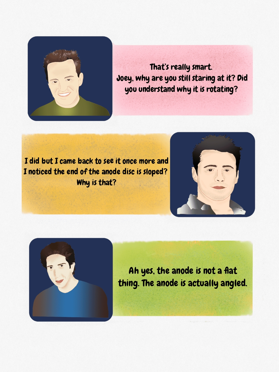 Discussion regarding the angled design of the anode disc in an X-ray tube, which relates to the concept of the actual versus effective focal spot.
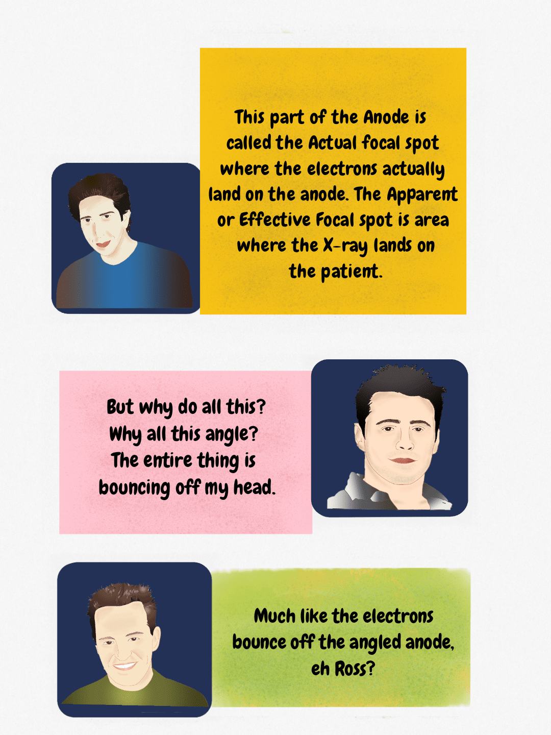 Diagram explaining the relationship between the actual focal spot (where electrons hit the anode) and the apparent/effective focal spot (where X-rays exit toward the patient).
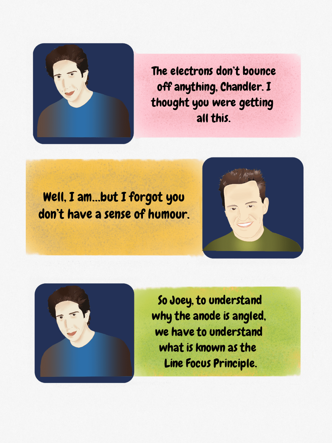 Teaching concept on X-ray tube physics, highlighting the Line Focus Principle and the angled anode.
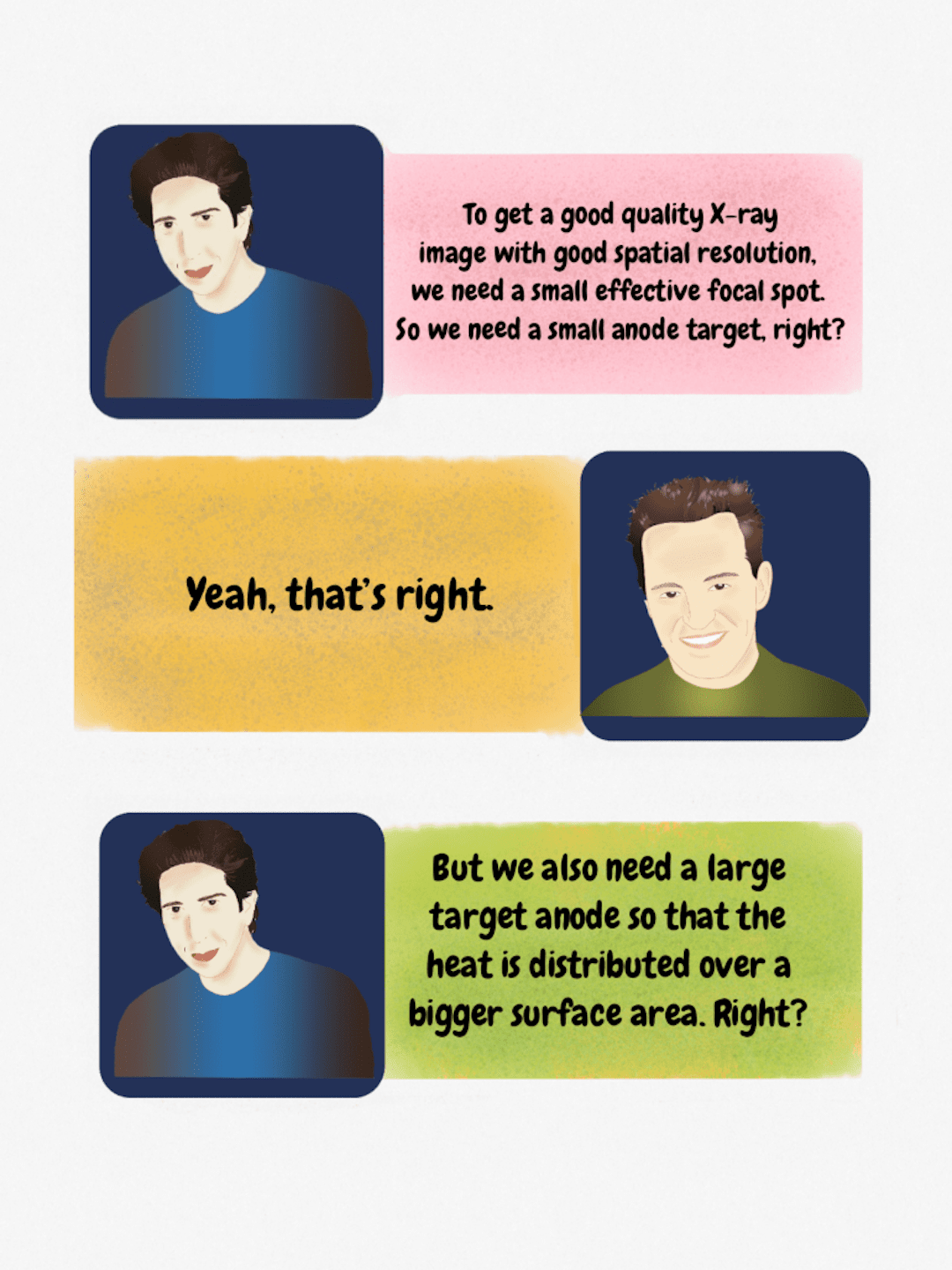 Figure illustrating the inverse relationship between the need for a small effective focal spot (for spatial resolution) and a large anode target (for heat distribution) in X-ray generation.
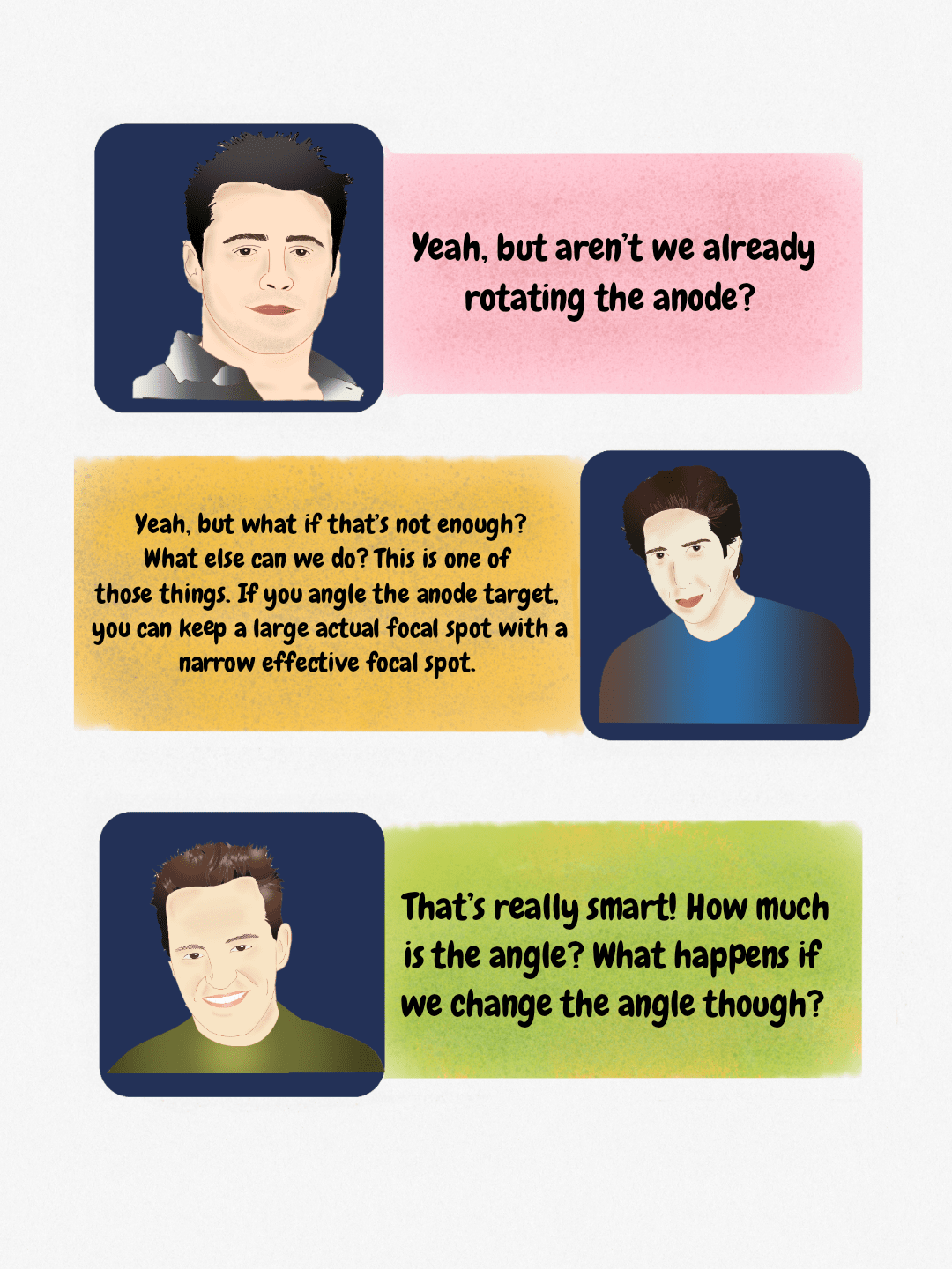 Discussion on X-ray tube focal spot control, emphasizing how anode angle manipulation creates a smaller effective focal spot.
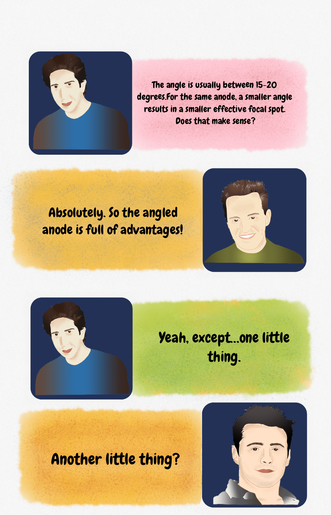 Dialogue discussing X-ray tube physics: a smaller anode angle yields a smaller effective focal spot.
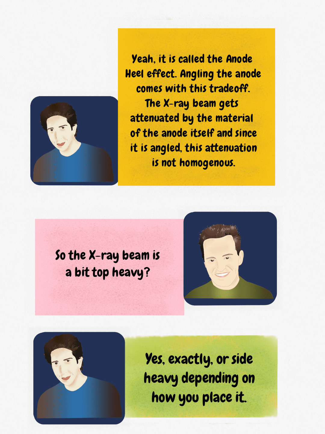 The Anode Heel effect results in non-homogenous X-ray beam intensity due to the angled anode.
 A humorous illustration contrasting the literal interpretation of 'top heavy' with its anatomical or physics-based meaning (above the belt).
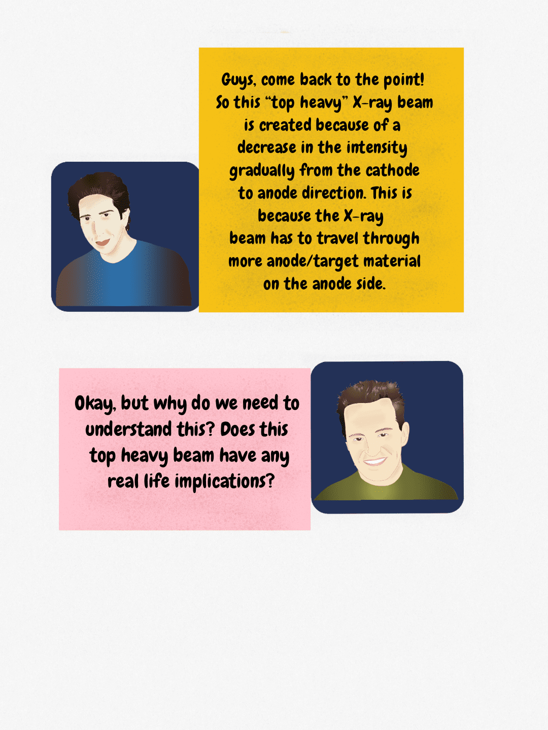 Explanation of the top-heavy X-ray beam phenomenon resulting from increased attenuation through the anode/target material.
 Radiography principle: Cathode side of the X-ray tube must be positioned toward the thickest part of the patient to ensure uniform exposure.
The line focus principle and anode angle
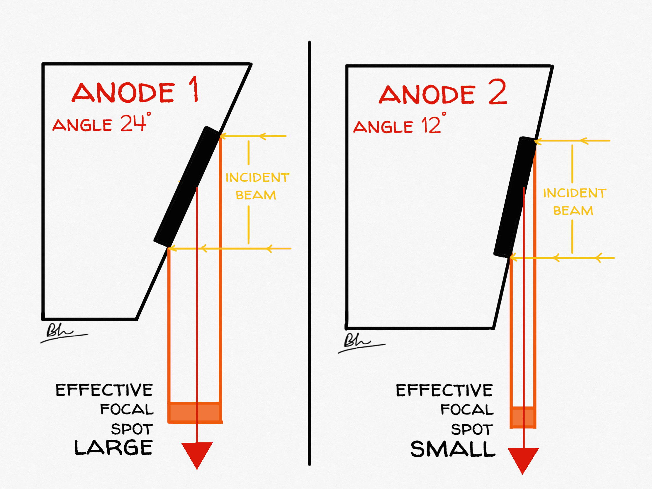
The target face is bevelled, typically at 7°–20° with 12° the commonest general-radiography angle. The electrons strike a long, narrow strip (the actual focal spot), but viewed from the patient that strip is foreshortened into a much smaller square (the effective focal spot):
Effective focal spot = actual focal spot length × sin (anode angle)
You get a large area for heat and a small source for sharpness from the same piece of tungsten. The trade-off is fixed by geometry:
| Making the anode angle steeper (smaller, e.g. 7°) | Making the anode angle shallower (larger, e.g. 17°) |
|---|---|
| Smaller effective focal spot, so better spatial resolution | Larger effective focal spot, so more geometric unsharpness |
| Greater heat loading for a given effective focal spot | Less heat loading for the same effective focal spot |
| More pronounced anode heel effect | Less pronounced anode heel effect |
| Smaller field coverage at a given distance: the beam is cut off on the anode side | Larger field coverage; needed for 35 × 43 cm work at short distances |
| Suits small-field, high-detail work such as angiography | Suits large-field general radiography and chest work |
A Monte Carlo analysis of anode tilt confirmed that the angle changes both the emitted photon fluence and the thermal load: the focal-spot temperature rise falls as the tilt angle increases, and altering the tilt from 8° to 28° together with the acquisition angle raised photon fluence by up to 55%.[1]
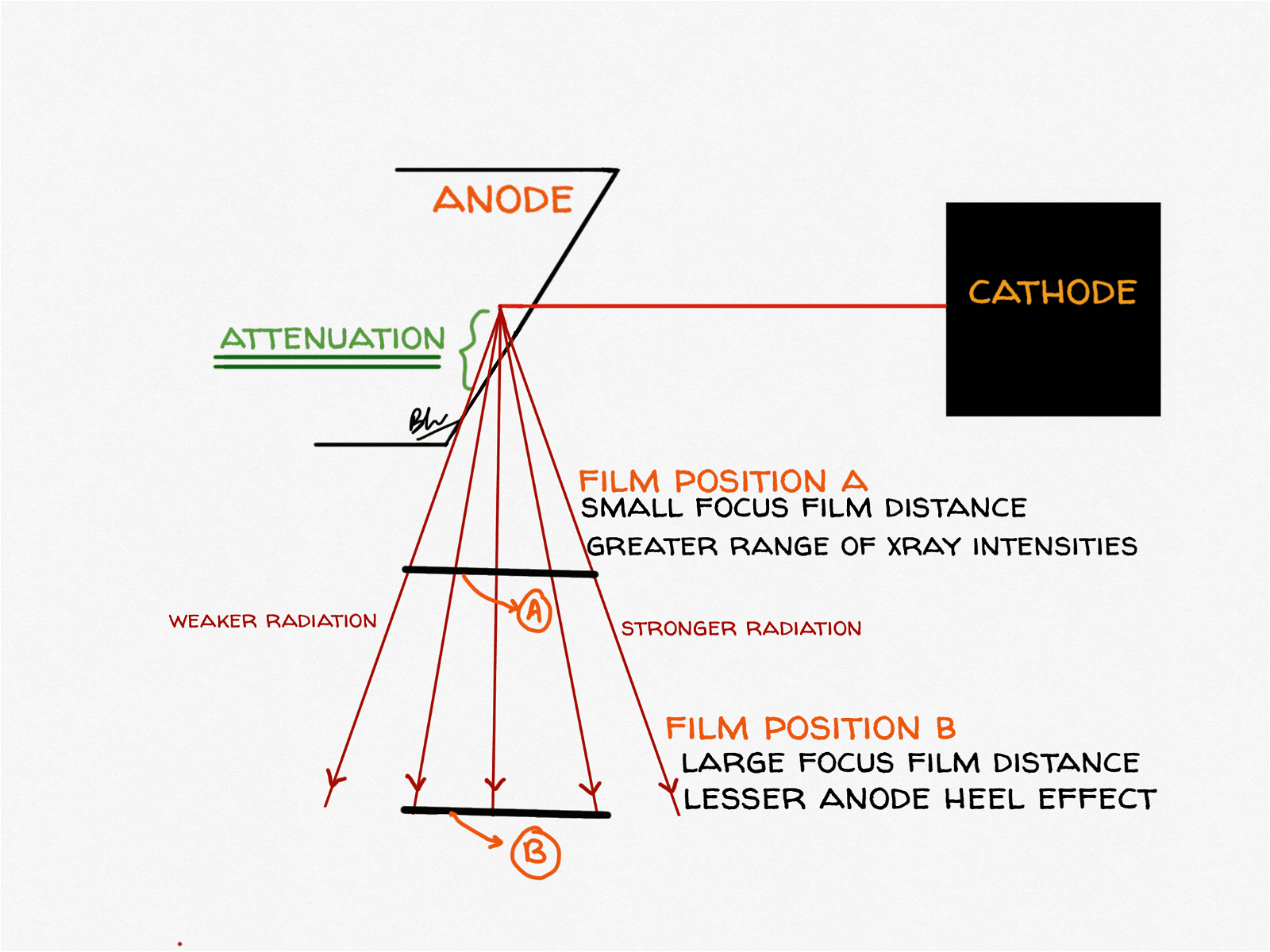
The anode heel effect explained
X-rays are produced a few micrometres inside the target, not on its surface. Photons emitted towards the anode side of the field must travel through a longer path of tungsten before escaping, so they are preferentially self-absorbed by the target itself: the “heel” of the anode. The result is a beam that is systematically weaker on the anode side and stronger on the cathode side, along the anode–cathode axis only. Across the perpendicular axis, intensity is essentially uniform.[2]
The effect is larger than most people assume, and it is not the same on every machine. Ionisation-chamber mapping of a 70 × 70 cm field on three general radiographic units found that at 85 kVp the average air kerma was 31.5%, 15.5% and 43.1% higher at the cathode end than at the anode end: a three-fold difference between machines in the same department. The same study confirmed the effect is significant only along the anode–cathode axis (p ≤ 0.03) and not across it (p ≥ 0.29).[2] An earlier phantom study measured a cathode-to-anode air dose ratio of 1.8.[3]
| The heel effect becomes more pronounced when… | Why |
|---|---|
| The anode angle is smaller (steeper target) | Longer path through tungsten for anode-side photons |
| The tube is older | Focal-track pitting and tungsten vaporised onto the envelope increase self-absorption |
| The tube potential is higher | Measured across 60, 85 and 110 kVp on all three units tested |
| The field size is larger | The field edges sit at more extreme angles from the target face |
| The source-to-image distance is shorter | A given cassette subtends a wider angular range of the beam |
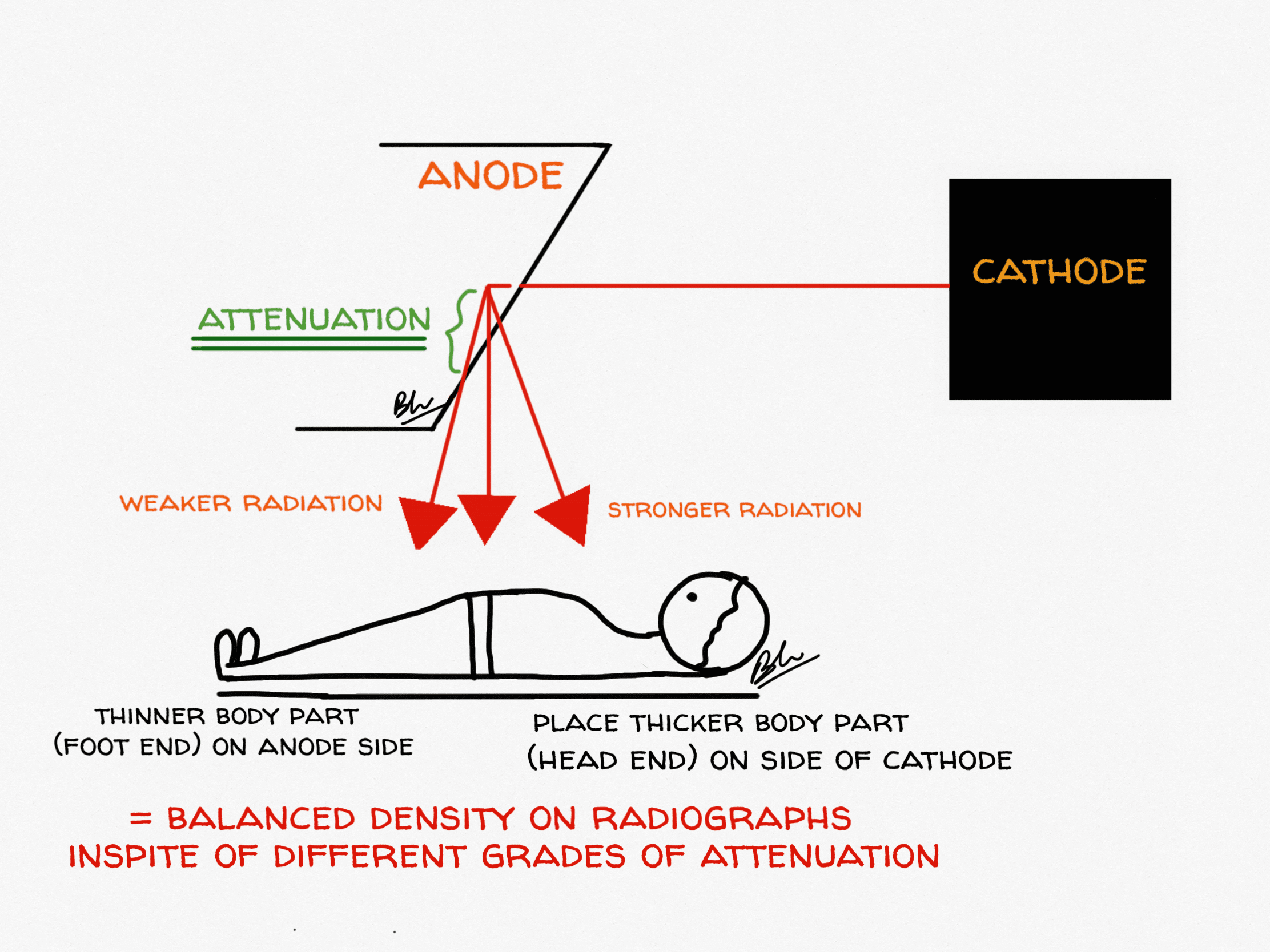
Using the heel effect: what the evidence actually shows
The classic teaching is to place the thicker end of the body part towards the cathode, where the beam is stronger, so that film density comes out even. That reasoning was written for film-screen radiography, where density could not be rescued afterwards. Digital radiography post-processing largely equalises the image, and a 2021 systematic review found only five heterogeneous studies, none with images assessed by radiologists, with contradictory technical and visual results. Its conclusion was blunt: the published evidence neither proves nor disproves an effect of anode orientation on image quality in DR, and no firm recommendation can be made on image-quality grounds.[4]
The dose argument is on much firmer ground. Because the cathode side genuinely delivers more radiation, turning the tube so that radiosensitive organs sit on the anode side reduces their dose without a penalty in acceptability:
| Projection | Orientation | Measured effect |
|---|---|---|
| AP pelvis | Feet towards anode | Significant reduction in testicular dose versus feet towards cathode (p < 0.001); no significant difference for ovaries[5] |
| AP pelvis | Feet towards anode | Optimum dose-plus-quality combination for both sexes; no adverse effect on visual image quality[6] |
| Lumbar spine AP and lateral | Head towards cathode | Reversing this (head towards anode) raised ovarian dose by 16%–17% and testicular dose by 12%–27%[3] |
| Paediatric chest | Anode end towards the face | Thyroid dose 12% lower and gonad dose 5.9% lower; all images still rated acceptable by five specialists[7] |
| Mammography | Chest wall towards cathode | Standard design; compensates for the thicker tissue at the chest wall |
Note the tension in the lumbar spine row. Anatomically the caudal end is thicker, so classic density-matching teaching would put the feet at the cathode: precisely the orientation that raises gonad dose. When image quality can be recovered digitally and dose cannot be un-delivered, the dose argument should generally win.
The focal effect: the other anode–cathode gradient
The heel effect has a less-taught twin. The effective focal spot is not one fixed size across the field: it is foreshortened most on the anode side and least on the cathode side, so the apparent source is smallest at the anode end and largest at the cathode end. Measurements across a 14 × 17 inch field using line-pair patterns found spatial resolution degrading by up to 75% from the anode end to the cathode end, an effect named the “focal effect”.[8]
So the two gradients point in opposite directions, and the practical rule is easy to remember:
- Cathode side: more photons, larger effective focal spot. Put the thicker part here.
- Anode side: fewer photons, smaller effective focal spot, lower dose. Put the part needing the finest detail, and any radiosensitive organ, here.
What has changed in tube technology
The tube in the diagram above is still the standard design, but high-end CT has moved well beyond it.
- Rotating-envelope tubes. Instead of a disc spinning inside a fixed envelope, the whole envelope rotates and the anode is cooled directly by the surrounding oil. The first clinical tube of this design achieved a cooling rate of 4.8 MHU/min (high enough to remove anode-cooling delays from the workflow entirely) and tolerates the 20 g forces of fast gantry rotation.[9]
- Liquid-metal spiral-groove bearings. These replace ball bearings with a gallium-based alloy film, running silently, conducting heat straight out of the anode and greatly extending tube life. They are now a standard differentiator among CT tube manufacturers alongside new target materials and superconducting designs.[10]
- Flying focal spot. Electromagnetic deflection makes the focal spot jump between positions between readings. The z-flying focal spot doubles z-sampling: it narrows the slice sensitivity profile by a factor of about 1.4, resolves 0.4 mm bars where 0.6 mm was the limit without it, and suppresses windmill artefacts even at pitch 1.5.[11]
- Photon-counting CT. The detector, not the tube, is what changed here, but the resulting demand for ever smaller, brighter focal spots is now the thermal bottleneck, and is driving focal-spot multiplexing and modified source designs.[10]
Quick revision table
| Question | Answer |
|---|---|
| What controls tube current (mA)? | Filament temperature, in the emission-limited region |
| What controls maximum photon energy? | kVp: the maximum photon energy in keV equals the kVp |
| Tungsten K-characteristic energies | K-alpha about 58–59 keV, K-beta about 67 keV; needs above 69.5 kVp |
| Effective focal spot formula | Actual focal spot length × sin (anode angle) |
| Typical anode angle | 7°–20°, commonly 12° |
| Rotating anode speed | 3,000–3,600 rpm standard; 8,000–10,000 rpm high-speed |
| Which side of the field is more intense? | The cathode side: by roughly 16%–43% at 85 kVp depending on the tube |
| Which side gives the sharpest image? | The anode side, because the effective focal spot is smallest there |
| Heat units | kVp × mA × s, multiplied by about 1.35 for three-phase and high-frequency generators |
Frequently asked questions
What is the anode heel effect?
The anode heel effect is the fall in X-ray beam intensity towards the anode side of the radiation field. X-rays are generated just below the target surface, and photons directed towards the anode side travel through more tungsten before escaping, so more of them are absorbed by the anode itself. Beam intensity is therefore higher on the cathode side, measured at 15.5%–43.1% higher at 85 kVp depending on the tube, and this variation occurs only along the anode–cathode axis.
Which side of the X-ray beam is stronger, anode or cathode?
The cathode side. One phantom study measured a cathode-to-anode air dose ratio of 1.8. The practical consequences are that the thicker part of the anatomy should be placed towards the cathode, and radiosensitive organs such as the gonads or thyroid should be placed towards the anode to reduce their dose.
What is the difference between a stationary and a rotating anode X-ray tube?
A stationary anode is a fixed tungsten button in a copper block, so every exposure heats the same small area; this limits tube current and is why stationary anodes are used only in dental and portable units. A rotating anode spins a tungsten-rhenium disc at 3,000–10,000 rpm, so the electron beam bombards a circular focal track rather than a single point. Spreading the heat over roughly two orders of magnitude more area allows far higher tube currents and smaller focal spots, which is why all general radiography, CT and angiography tubes use rotating anodes.
What is the line focus principle?
The line focus principle is the use of a bevelled anode so that a large actual focal spot projects as a small effective focal spot. The effective focal spot equals the actual focal spot length multiplied by the sine of the anode angle. This gives a large surface area to absorb heat while keeping the apparent X-ray source small enough for a sharp image. The unavoidable side effect is the anode heel effect.
Does a smaller anode angle make the heel effect worse?
Yes. A smaller (steeper) anode angle means anode-side photons traverse a longer path through the target, so self-absorption increases. Measurements across three radiographic units confirmed that the heel effect was more pronounced with a smaller anode target angle, with greater tube age, and at higher tube potentials.
Does the anode heel effect still matter in digital radiography?
For image quality, the evidence is weak. A 2021 systematic review found only five heterogeneous studies with contradictory results and concluded that no firm recommendation on anode orientation can be made for image quality in digital radiography. For radiation dose, the effect is real and reproducible: orienting the patient so that the gonads or thyroid lie on the anode side measurably lowers their dose, with reductions of about 6%–27% reported across pelvis, lumbar spine and paediatric chest studies.
Why is tungsten used as the anode target material?
Tungsten combines a high atomic number (Z = 74), which makes bremsstrahlung production relatively efficient, with a melting point of 3,422 °C and good thermal conductivity, which let it survive the heat. Diagnostic targets are alloyed with roughly 5%–10% rhenium to resist surface crazing with repeated thermal cycling, and bonded to a molybdenum or graphite disc that adds heat capacity without adding much rotating mass.
Did you like it? Or as Chandler would ask: can X-ray physics BE any more interesting? Let us know in the comments. Next episode: The One with The X-Ray Interactions. Check the front page for updates.
References
- Ou Hadda H, Zerfaoui M, Bahhous K, et al. Impact of the anode tilt on photon emission spectrum and temperature rise in an x-ray tube. Biomed Phys Eng Express. 2022;9(1). PMID: 36562508. doi:10.1088/2057-1976/acab6c
- Chan CTP, Fung KKL. An Investigation on the Non-uniform Distribution of Radiation Intensity Output of Diagnostic X-ray Tubes. J Med Imaging Radiat Sci. 2014;45(3):223–229. PMID: 31051973. doi:10.1016/j.jmir.2014.04.006
- Fung KK, Gilboy WB. “Anode heel effect” on patient dose in lumbar spine radiography. Br J Radiol. 2000;73(869):531–536. PMID: 10884750. doi:10.1259/bjr.73.869.10884750
- Kusk MW, Jensen JM, Gram EH, Nielsen J, Precht H. Anode heel effect: Does it impact image quality in digital radiography? A systematic literature review. Radiography (Lond). 2021;27(3):976–981. PMID: 33741222. doi:10.1016/j.radi.2021.02.014
- Mraity HA, England A, Hogg P. Gonad dose in AP pelvis radiography: Impact of anode heel orientation. Radiography (Lond). 2017;23(1):14–18. PMID: 28290334. doi:10.1016/j.radi.2016.06.003
- Mraity HAAB, Walton L, England A, Thompson J, Lanca L, Hogg P. Can the anode heel effect be used to optimise radiation dose and image quality for AP pelvis radiography? Radiography (Lond). 2020;26(2):e103–e108. PMID: 32052763. doi:10.1016/j.radi.2019.11.094
- Daruich De Souza C, Rico Freitas G, Fachel Medeiros R, et al. Protocol for reducing radiation exposure during pediatric thoracic radiography. J Med Imaging Radiat Sci. 2022;53(3):437–443. PMID: 35750602. doi:10.1016/j.jmir.2022.05.012
- Katz MC, Nickoloff EL. Radiographic detail and variation of the nominal focal spot size: the “focal effect”. RadioGraphics. 1992;12(4):753–761. PMID: 1636037. doi:10.1148/radiographics.12.4.1636037
- Schardt P, Deuringer J, Freudenberger J, et al. New x-ray tube performance in computed tomography by introducing the rotating envelope tube technology. Med Phys. 2004;31(9):2699–2706. PMID: 15487753. doi:10.1118/1.1783552
- Zhang H, Ji Z, Jiang R. Advances in X-Ray Tube Technology for CT Systems: Key Component Innovation. Zhongguo Yi Liao Qi Xie Za Zhi. 2025;49(4):383–388. PMID: 40948278. doi:10.12455/j.issn.1671-7104.240563
- Kyriakou Y, Kachelriess M, Knaup M, Krause JU, Kalender WA. Impact of the z-flying focal spot on resolution and artifact behavior for a 64-slice spiral CT scanner. Eur Radiol. 2006;16(6):1206–1215. PMID: 16541229. doi:10.1007/s00330-005-0118-9

Improve Content And Help Your Colleagues!
Found an error in the post? Please let us know using our contact page and we will update it with due credits!
If you wish to contribute radiological images for this case (or any other article on the website), you can submit them here and you will be duly credited: Submit radiology case
Good for remembering, please go on with some difficult topics. Please don’t stop this innovative idea.
Sure! Glad you liked it, Dinesh!
I am impressed by how clearly radiology physics is explained, accompanied by excellent diagrams. Thank you to the entire team.
Mohan
Glad you liked it.
It’s a very interesting.
Kindly update for usg ,ct ,Mri and pet-ct ,spect-ct physics.
We are working on it and it should be up soon! Thank you for your feedback, Harsh!
very interesting and informative .
Thank you! Hope you checked the second episode in the series here: https://radiogyan.com/physics/the-one-with-the-x-ray-interactions/
woow amazying ……
Glad you liked it, Praveen.